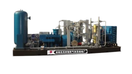
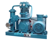
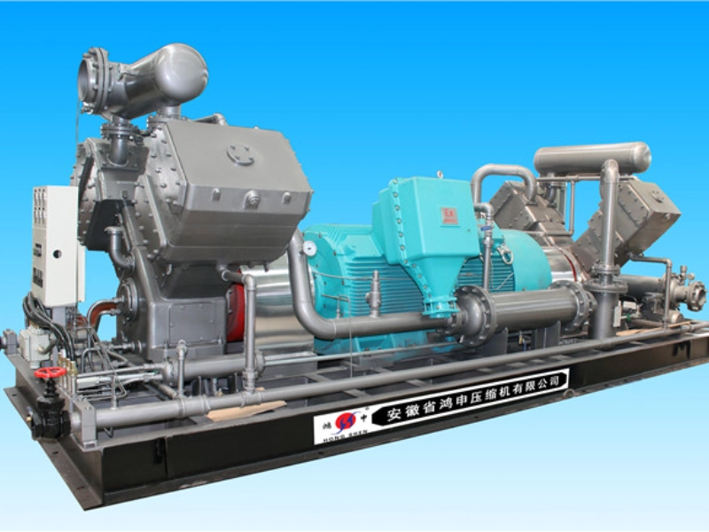
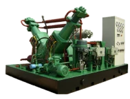
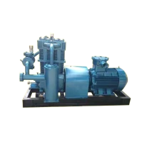
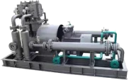
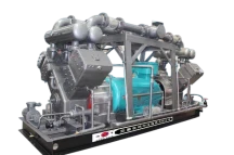
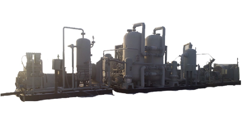
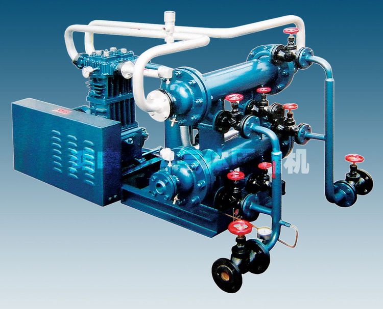
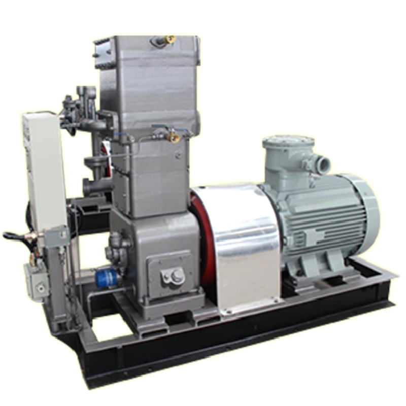
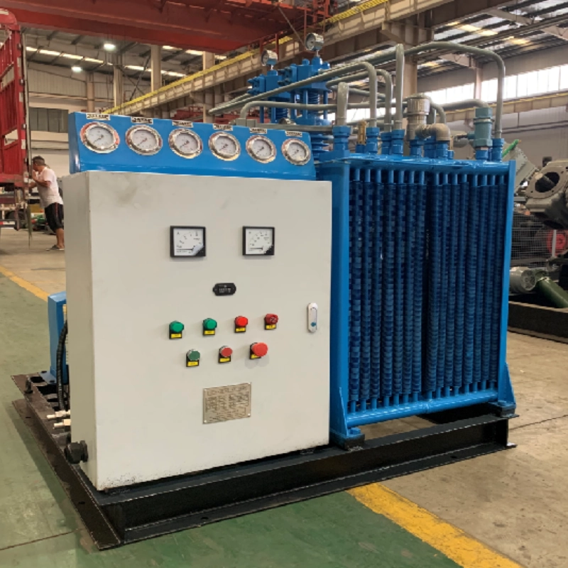
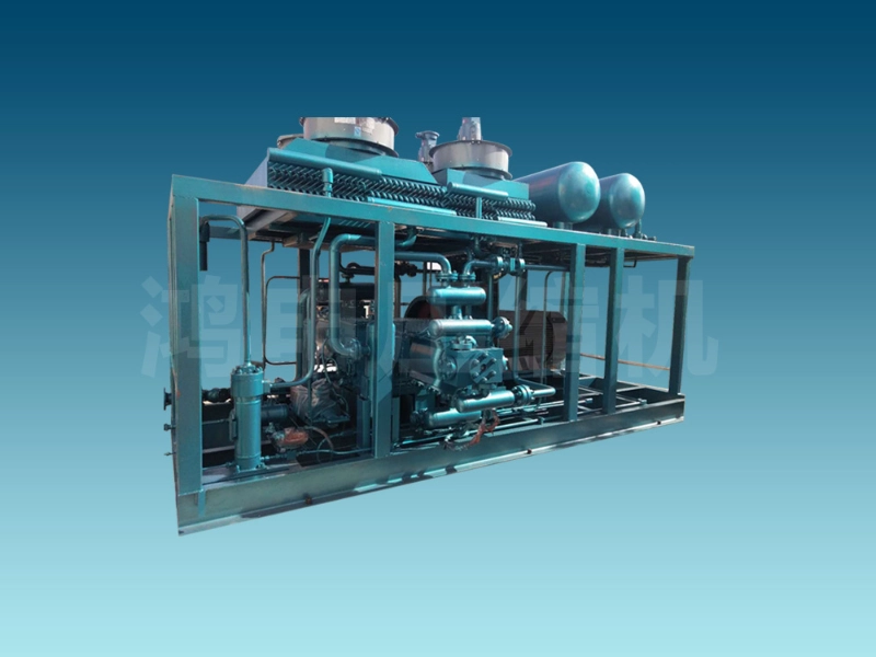
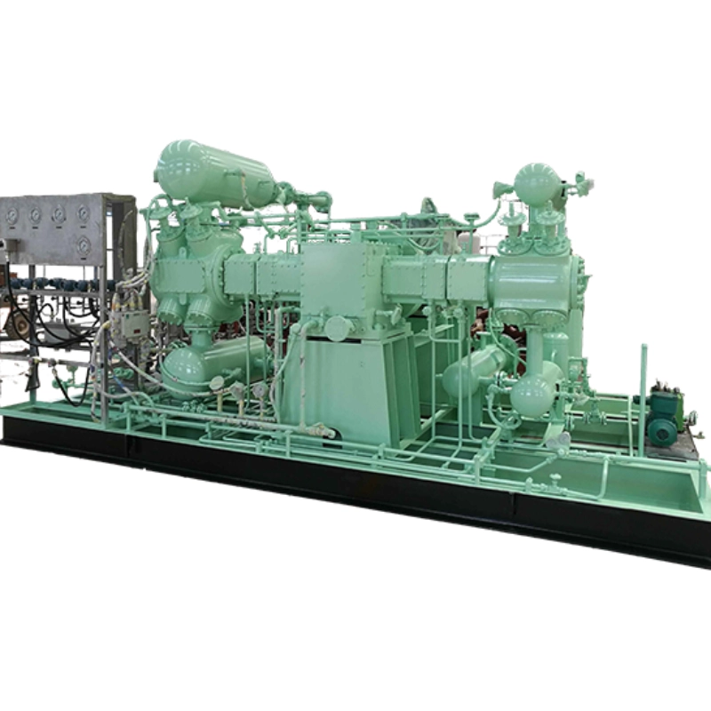
Oilfield gas lift compressor is a common piece of industrial equipment that works by compressing incoming air or gas to lift oil from the bottom of the well to the surface.
Schematic diagram of unloading process
Liquid conveying
At the beginning, open the liquid phase pipe of the tanker in the storage tank, if the liquid level in the tanker is higher than that in the storage tank, it will flow into the storage tank automatically, and when it reaches the equilibrium, the flow will be stopped. If the liquid level in the tank car is lower than the storage tank, start the compressor directly, the four-way valve is in the positive position, the gas is extracted from the storage tank through the compressor and pressurised and then discharged into the tank car, at this time the pressure in the tank car rises and the pressure in the storage tank falls, and the liquid in the tank car flows into the storage tank under the action of the pressure difference. (As shown in the figure below)

Residual gas recovery
When the unloading is completed, the bottom of the tanker leaves part of the residual night as well as the saturated gas in the full tank, and the user needs to recover this part of the medium, the four-way valve is reversed to the opposite position, and the liquid phase pipeline is closed. At this time, the remaining saturated gas in the tanker is sucked in by the compressor, pressurised and discharged to the storage tank, and the pressure in the storage tank rises, exceeding the saturation pressure of the gas phase so that the gas phase is liquefied to achieve the purpose of recovery. While the pressure inside the tanker drops, the liquid phase will continue to gasify until the liquid gasification is completed, and the gas phase pressure drops to the compressor’s working condition allowable value and then stops recovery. (Note: When the residual gas is recovered, a cooler can be added at the exhaust end to facilitate the recovery)
Working principle of four-way valve
Trigger the four-way valve handle, when the four-way valve is in the position shown in Figure a, then the A end of the inlet, the gas flows from A to B, through the receiver, inlet filter parts, compressor inlet pipe, compressor, compressor exhaust pipe, D end of the flow to the C end, C end of the exhaust end.

When the four-way valve is in the position of B in the figure, then the C end is the inlet, the gas flows from the C end to the B end, through the receiver, the inlet filter parts, the compressor inlet pipe, the compressor, the compressor exhaust pipe, the D end flows to the A end, the A end is the exhaust end.

